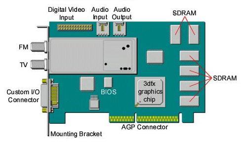
The board diagram below shows the 3dfx Voodoo3 3500 TV card. Note the locations of the Custom I/O Connector, the FM and TV tuner input connectors, the Audio Output and Audio Input connectors, and the Digital Video Input Connector (CCR-601) on the Voodoo3 3500 TV card.
Voodoo3 3500 TV AGP
| Table of Connectors on the Mounting Bracket | Top |
Connector |
Connects to... |
| FM Antenna Input | FM Radio signal from a standard FM antenna |
| TV Antenna Input | Broadcast-level (RF) video signal from Cable TV or antenna |
| Custom I/O Connector | The included Custom I/O Cable and the A/V-I/O Pod |
| The Custom I/O Cable Diagram |
| The A/V-I/O Pod Diagram |

IMPORTANT NOTES: The Left and Right Audio Inputs are used for the audio signals that accompany a video source connected to either the Composite Input or the S-Video Input. If no audio source is connected to these audio inputs, then you will get no accompanying audio signal when you select the Composite or S-Video input option, and no audio will be recorded if you try to record a video file from one of those sources. When the Tuner option is selected, then the accompanying audio signals are also provided by the Voodoo3 3500 TV card's tuner. The Left and Right Audio Outputs on the A/V-I/O Pod cannot provide the entire audio output for your computer. The audio signals delivered through these connectors comes only from the Voodoo3 3500 TV card's tuner, or from the Left and Right Audio Input connectors on the A/V-I/O Pod, or from an internal audio device in your computer that you have connected to the Audio Input connector on the Voodoo3 3500 TV card (like a CD-ROM drive's audio output cable). |
| Bus Slot Diagram |
The diagram below shows a typical layout of bus slots inside a computer. Compare the diagram to your computer to identify the appropriate slot for your new card.

| VGA Connector Diagram |
A diagram of the Monitor Connector on the Custom I/O Cable for your Voodoo3 3500 TV card is shown below along with a table of the corresponding display signals.
 |
Pin 1 | Red |
| Pin 2 | Green | |
| Pin 3 | Blue | |
| Pin 4 | (none) | |
| Pin 5 | Self Test | |
| Pin 6 | Red Return | |
| Pin 7 | Green Return | |
| Pin 8 | Blue Return | |
| Pin 9 | DDC power (+5V) | |
| Pin 10 | Digital Ground | |
| Pin 11 | Digital Ground | |
| Pin 12 | DDC-2B Data | |
| Pin 13 | Horizontal Sync. | |
| Pin 14 | Vertical Sync. | |
| Pin 15 | DDC-2B Clock |
| Digital Video Input Connector |
A diagram of the Digital Video Input Connector (CCIR-601) on your Voodoo3 3500 TV card is shown below along with a table of the corresponding input signals:
 |
Pin 1 | Ground |
| Pin 2 | Data (0) | |
| Pin 3 | Ground | |
| Pin 4 | Data (1) | |
| Pin 5 | Ground | |
| Pin 6 | Data (2) | |
| Pin 7 | (none) | |
| Pin 8 | Data (3) | |
| Pin 9 | (none) | |
| Pin 10 | Data (4) | |
| Pin 11 | (none) | |
| Pin 12 | Data (5) | |
| Pin 13 | SCL | |
| Pin 14 | Data (6) | |
| Pin 15 | Ground | |
Pin 16 |
Data (7) | |
| Pin 17 | Ground | |
| Pin 18 | Video Clock | |
| Pin 19 | Ground | |
| Pin 20 | (none) | |
| Pin 21 | Ground | |
| Pin 22 | (none) | |
| Pin 23 | (none) | |
| Pin 24 | (none) | |
| Pin 25 | SDA | |
| Pin 26 | Ground |